This documentation is a work in progress! We are updating regularly so check back soon.

Wiring

V1.6 Control

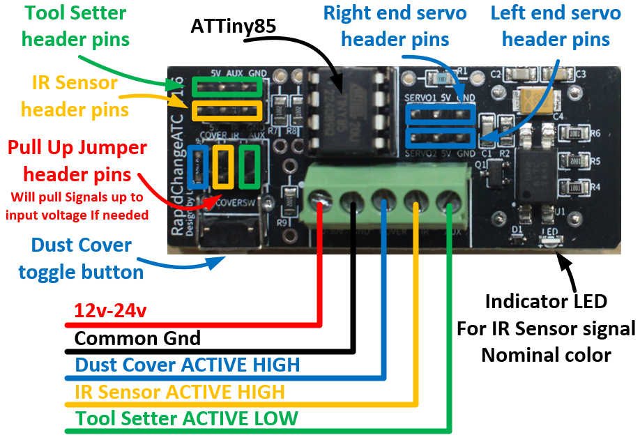
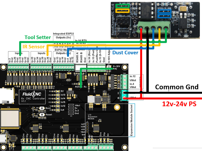
The wiring pictured below is color coded to the cable coming from the magazine for Premium models.
Basic models with a tool setter will have a blue wire connected to the tool setter.

Control Board Layout
6X CNC Controller V1.1

Most FluidNC controllers have internal pull up resistors so the onboard pull up jumpers are not needed.
The wiring diagram below will be universal with 6 pack controllers like Elecrew and PiBot.
YAML FILE ADDITIONS

Spindle Section

The last line of the spindle section tells FluidNC where to find the TC.nc Macro that handles the tool changes.

The Macros can be stored either on the local FS or on an SD card. Only use one.
The example below shows it being stored on the SD card and the local FS is commented out.

User IOs

The Dust Cover output and IR Sensor input must be assigned in the user outputs/inputs section as in the example below. Use the appropriate GPIOs for your board.


In the web UI the output in this example would be designated P0 and the input as P1

Tool Setter

The Tool Setter can be assigned to the probe pin or the tool setter pin.

An unhandled error has occurred. Reload 🗙