Wiring
V1.6 Control
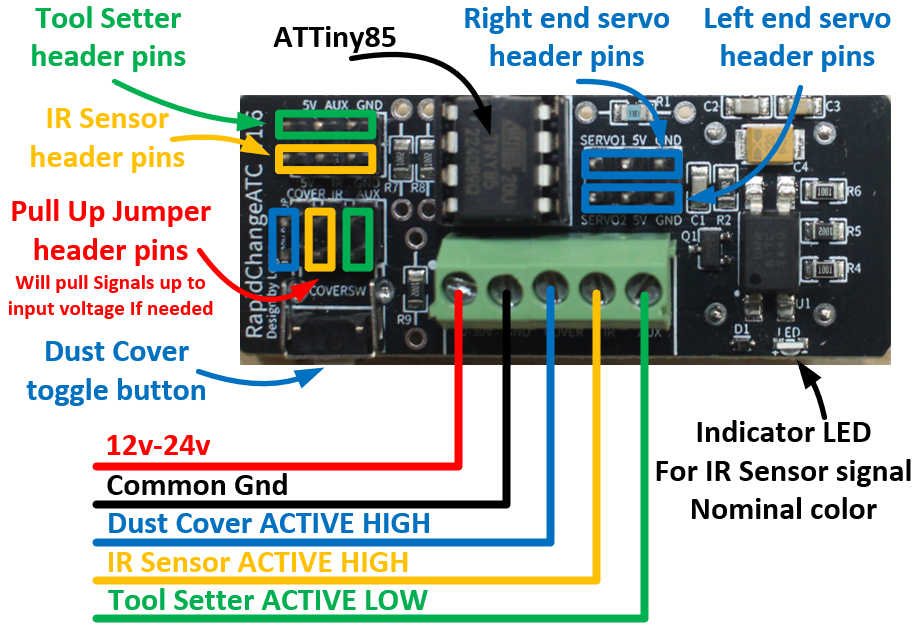
The wiring pictured below is color coded to the cable coming from the magazine for Premium models.
Basic models with a tool setter will have a yellow wire connected to the tool setter.
Control Board Layout
Specific Controllers
Diagrams for various controllers and breakout boards
Wiring connection locations are just an example. Please make sure your ATC is wired to a open port of the appropriate type and adjust your software configuration accordingly.
Output/Input ports must be an isolated port to function properly.
ABBXE
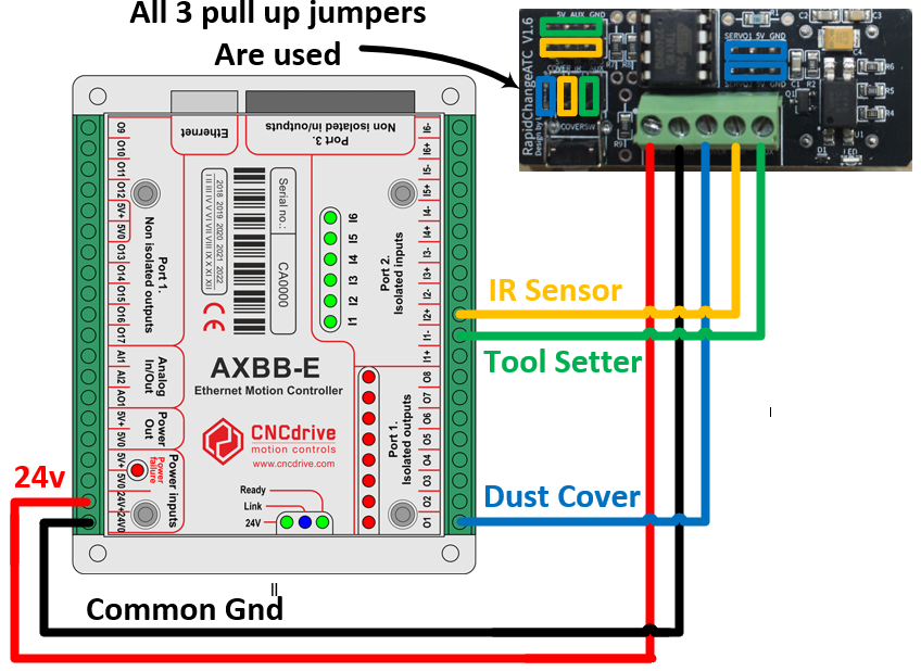
Port 1 Output 1 can not be used for the dust cover as it is used for the charge pump
C94
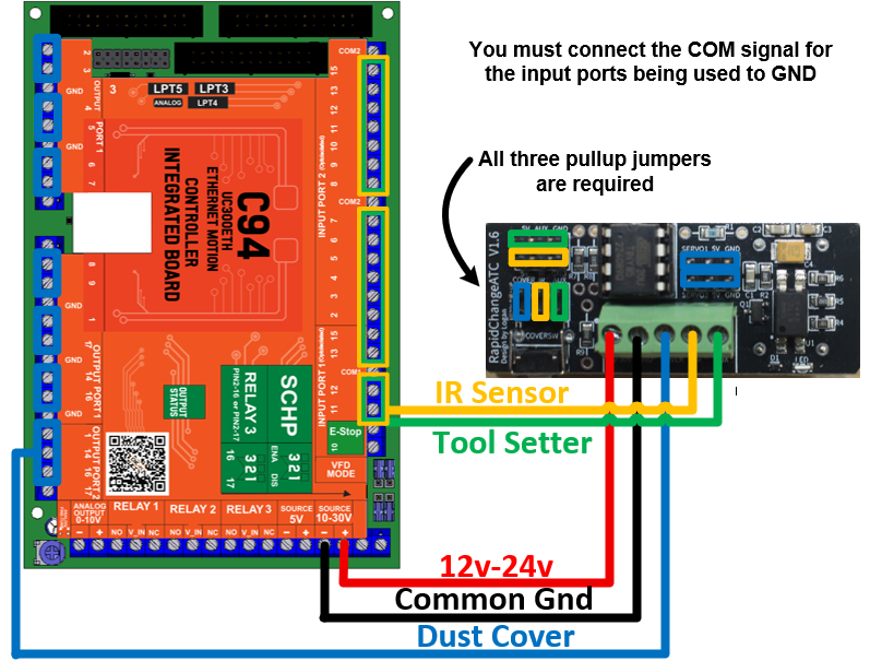
Port 2 Output 17 can not be used for the dust cover as it is used for the charge pump
More controller diagrams will be available soon.