Pocket Positions
Pocket positions are determined by a single reference position on each of the X, Y and Z axes. The reference positions must be determined using your machine and then recorded in your RapidChange profile. MACHINE COORDINATES should be used for all positions.
Profile Section
Pocket positions are configured with X, Y, and Z axis position fields for each pocket. Only Pocket 1 fields are editable. All others are calculated. When a position is updated for Pocket 1, the other pockets are updated accordingly.

Fields
This section has three editable fields for Pocket 1. Clicking on any field in the Pocket 1 row will enter edit mode.

When you are satisfied, click  to save your changes or
  to discard.
X Position
X MACHINE COORDINATE position of the center of the pocket.
Y Position
Y MACHINE COORDINATE position of the center of the pocket.
Z Position
Z MACHINE COORDINATE reference position of the magazine.
When the Z Position value is updated, Zone 1 and Zone 2 in Tool Detection are adjusted according to the offsets in Z Position Offsets. Z Engage is calculated according to the Z Engage Offset in Z Position Offsets

Options
Show All Pockets
Displays pocket positions for every pocket when selected.
Tool Setter Pocket(Compatible magazines only)
Allows for configuring the tool setter as occupying a pocket in the magazine.
When the Tool Setter Pocket value is updated, if either First or Last is selected, the number of pockets in the magazine will be reduced by one. The X and Y Positions for the Tool Setter are also set automatically to the calculated position of the appropriate pocket from the Pocket 1 reference positions.
Find X and Y Positions
Attach the locator disc and 1 1/2" x 1/4" dowel pin to your spindle.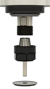
Thread the assembly by hand onto the spindle shaft until it is snug (hand-tight). Jog the spindle over Pocket 1 and mate the locator disc with the pocket. Adjust in X and Y using the disc as a visual indicator until the spindle is centered in the pocket. Increments of 0.1mm (0.004in) will be within tolerance.
Record the MACHINE COORDINATES for the X Position and the Y Position.
Being off center by 0.5mm, 0.020" or more may result in occasional failures loading and unloading. If you within this tolerance and are still having issues with failures, check the tram of the spindle.
It is recommended to ensure that the threads of your clamping nuts are free from burrs or sharp edges before placing them in service and to dress the starting thread on your spindle with some Emory cloth or a fine toothed file, just enough to roll any sharp edges.
Find Z Position
Apart from clearance heights used for travelling in the XY plane, all Z positions used for ATC operations are calculated from the Z Position. This is the position at which the line of sight of the IR sensor beam is first restored with a fully threaded clamping nut attached to the spindle coming up out of the pocket.
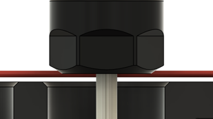
Use the Find Z Position macro to automatically detect the Z Position value for your installation.
Position the spindle with a tool attached in into it's pocket enough to break the line of sight of the IR sensor beam as shown below.
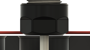
Run the Find Z Position macro from this position. The spindle will move up until the line of sight is restore and you will be prompted to record the current Z MACHINE COORDINATE into the Z Position field.