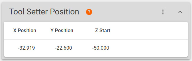
Tool Setter Position
The Tool Setter Position defines where your tool setter is on your table and gives the position from
Any tool number that exceeds the number of pockets in your magazine will be treated as a manual tool.
Tool Setter Placement
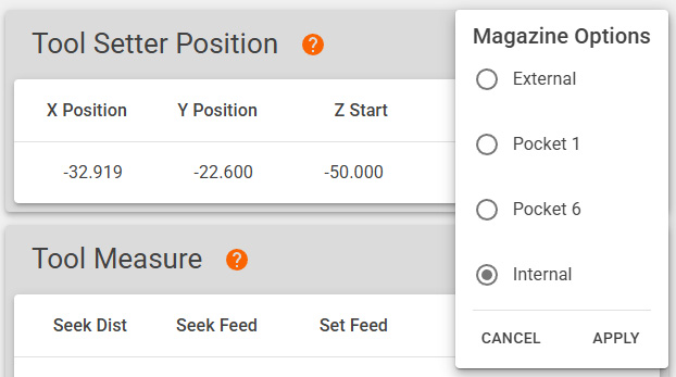
Older magazines had the option for the tool setter occupying a position within the magazine.
Now we offer a tool setter that is located within the magazine. A tool setter may also be used that is external to the magazine. This placement must be chosen in the "more options" section. Choose the appropriate placement for your machine.
This option determines when the dust cover will close.
With an External tool setter the dust cover closes before measuring the tool.
With an Internal tool setter the dust cover closes After measuring the tool.
Fields
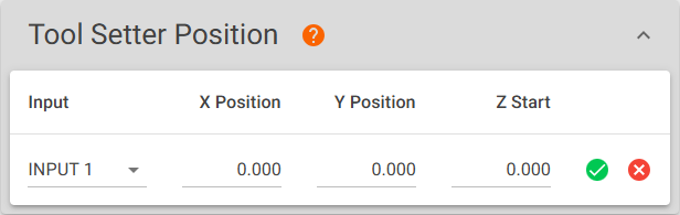
This section contains four editable fields: Input, X Position, Y Position, and Z Start. Click on any of the fields to open edit mode.
When you have entered the desired values, click the green check-mark to save your changes.
X Position
X MACHINE COORDINATE position of the tool setter.
Y Position
Y MACHINE COORDINATE position of the tool setter.
Z Start
Z MACHINE COORDINATE position that the spindle will move to after moving in the XY plane above the tool setter and before beginning the Tool Measurement routine.
Profile Section
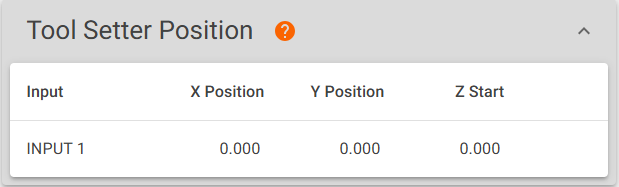
Fields
This section contains four editable fields: Input, X Position, Y Position, and Z Start. Clicking on any of the fields will enable editing.
When you are satisfied, click  to save your changes or
  to discard.
Input
The input designation that you chose in the Centroid UI for the tool setter. The available values are INPUT 1 through INPUT 8.
X Position
X MACHINE COORDINATE position of the tool setter.
Y Position
Y MACHINE COORDINATE position of the tool setter.
Z Start
Z MACHINE COORDINATE position that the spindle will move to after moving in the XY plane above the tool setter and before beginning the Tool Measurement routine.
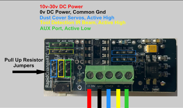
Wiring
By Default the Optical Tool Setter will be connected to the AUX port.
On premium magazines the Aux Port will be a green wire and with Basic magazines the Aux Port will be the blue wire.
Optional Wiring
If you would like to have the indicator LED on the magazine to light when the tool setter is triggered you may swap the IR sensor and Aux Port Header pins.